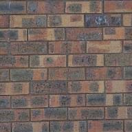
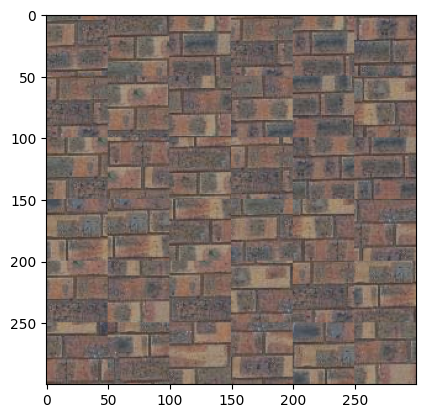
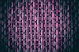
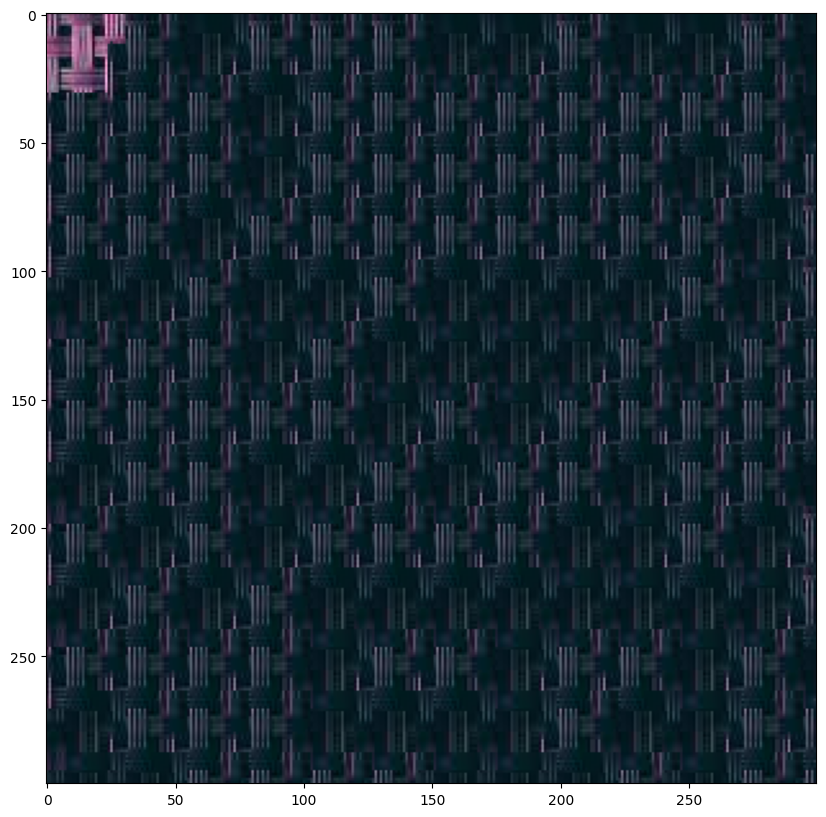
For the first part, the quilt_random function creates a image by randomly sampling square patches from an input/texture image and assembling them in a grid-like fashion. It dynamically calculates the number of patches needed and ensures patches are sampled within valid bounds to avoid out-of-range errors. It also adjusts patch sizes near the edges to fit within the output dimensions. The patch size was chosen to be 50 (high) to replicate the texture of the bricks. The output size was 300. Below is the original image (first) displayed next to the randomly sampled output (second). As you can see, the output is not bad qualitatively, but still requires a smoother overlap.


Moving on, the quilt_simple function improves on the previous method by quilting overlapping patches from the sample image to create a better output. The function works by dividing the output into a grid of patches, aligning them with a specified overlap to ensure smooth transitions between patches. The first patch is selected randomly, and then subsequent patches are chosen based on minimizing the Sum of Squared Differences (SSD) between the overlapping regions of the existing output and candidate patches from the sample image. The 'ssd_patch' helper function computes the SSD for a masked template over all possible patch positions in the sample, and 'choose_sample' selects a random patch among the top 'tolerance' lowest-cost candidates. For this part, the patch size was 53, overlap was 20 and tolerance was 3.
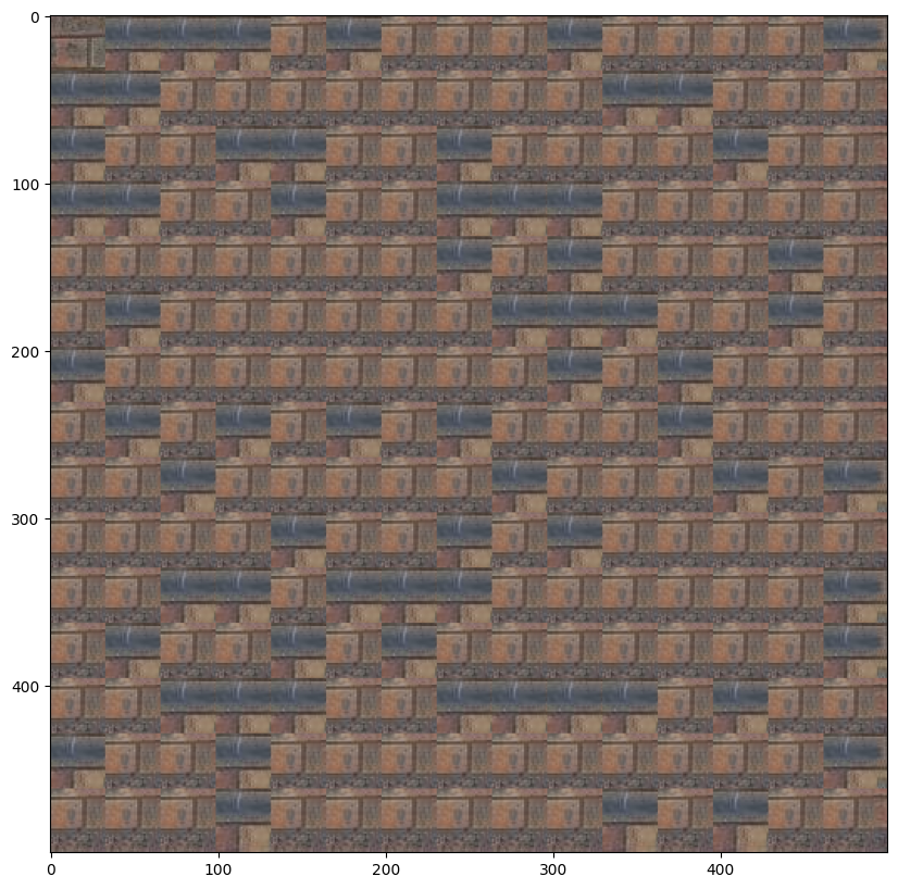
The quilt_cut function creates a texture by quilting overlapping patches from a sample image, using minimum-cost seam cutting to ensure smooth transitions between patches. For each patch, it calculates overlaps with previously placed patches, determines the optimal seam for blending using a mask, and integrates the new patch while minimizing visible seams. The function relies on compute_seam_cost to evaluate the cost of mismatches in overlapping regions, applying the seam mask only within overlap areas.

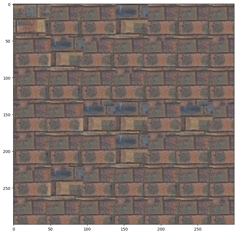
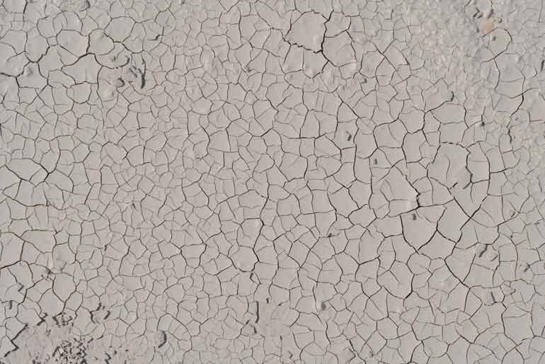
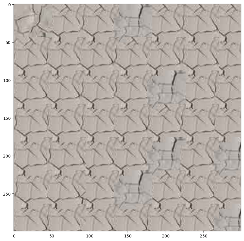
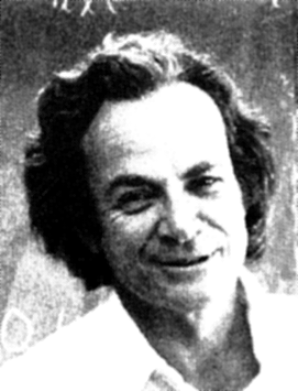
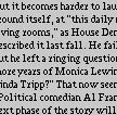
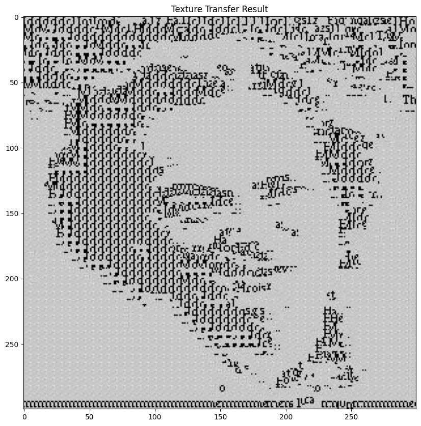
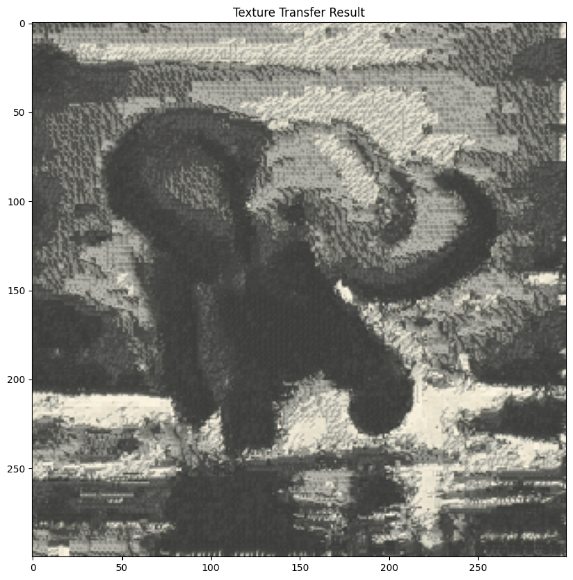
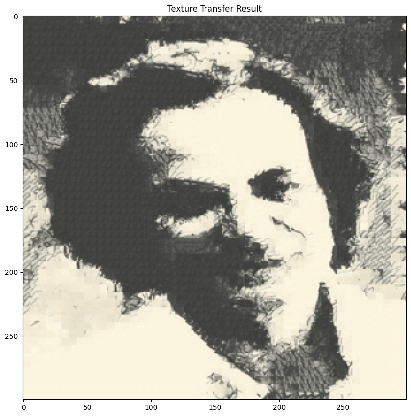
The texture_transfer function combines texture synthesis with a guidance image to transfer the visual style of a sample image onto the structure of the guidance image. It divides the output into overlapping patches and determines the best-fitting patch for each location based on a weighted combination of overlap consistency (using ssd_patch) and similarity to the corresponding region in the guidance image (using ssd_guidance). The balance between these criteria is controlled by the parameter alpha. The function begins by randomly sampling the first patch and progressively places subsequent patches, aligning them with both the texture sample and the guidance structure.



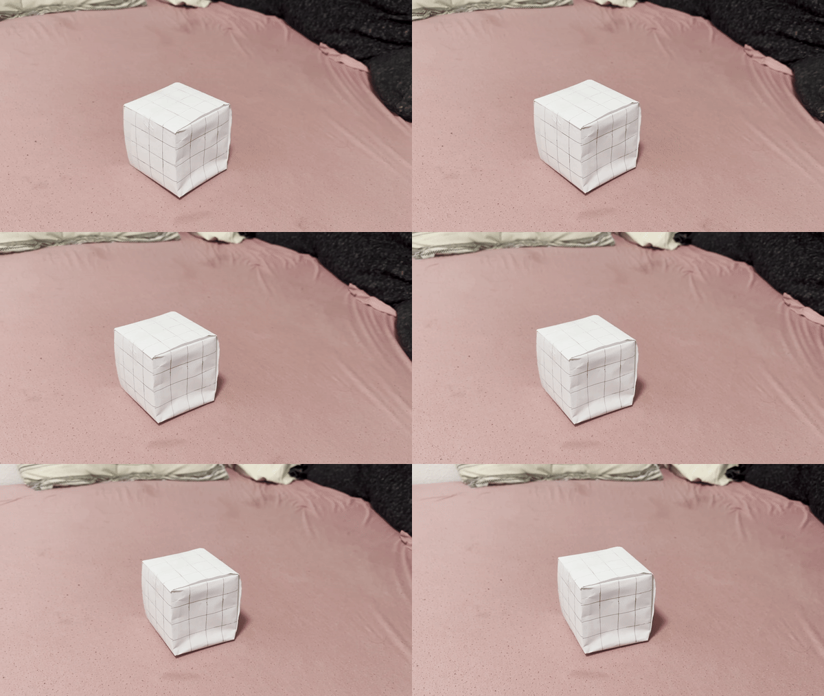
I chose a white box for the video, and drew a regular grid pattern over it to define the points. The video is shown below. The code then opens a video file using OpenCV (cv2.VideoCapture) and then enters a loop that reads each frame one by one using video.read(). For each frame, it saves it as a JPEG image in the output folder.
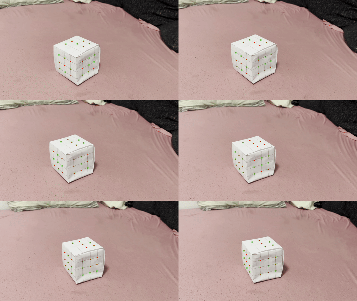
This code implements a point tracking system that tracks multiple points across video frames. It uses OpenCV's CSRT tracker to follow the movement of specified points, creating a bounding box around each point and tracking their positions frame by frame. The results are saved as both annotated video frames (showing the tracked points) and a JSON file containing the tracking data, which includes the coordinates and bounding box information for each point throughout the video sequence. The 2D points (24 points) for this part were generated using the correspondence tool and imported in json format.
For this part, I established a 3D-2D point correspondence system that computes a projection matrix. It first loads 2D points from a JSON file, then defines 3D coordinates for the cube structure (with left, front, and top sides with specific measurements), and finally uses these corresponding points to calculate a camera projection matrix using a homogeneous linear system solved through singular value decomposition (SVD).
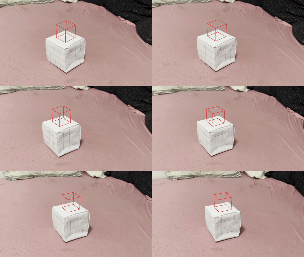
We now draw a 3D cube on a sequence of video frames using a projection matrix. For each frame, the code takes a base point in 3D space, projects the cube's vertices onto the 2D image plane using the computed projection matrix, and then draws red lines connecting these projected points to create a cube visualization. The process is repeated for all frames (0-133) and saves the annotated images with the drawn cube.
I have taken some inspiration from ChatGPT and pretrained LLM's to create the structure for some parts of the website.
Back to Main Page